


【3D Printing】Unboxing the Bambu Lab A2L Combo!
3DMart is an official authorized dealer of Bambu Lab. You are welcome to schedule a visit to see the A2L in person!

Package Contents

Part 1: Unboxing Guide
Remove Packaging and Take Out Accessories
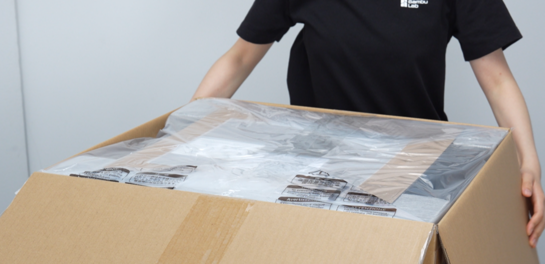
Step 1: Remove Packaging
-
Cut open the outer box, tear open the moisture-proof bag, and place the moisture-proof bag over the outer box.
-
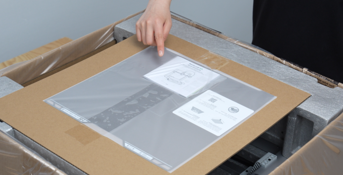
Carefully read the quick guide to familiarize yourself with unboxing precautions.
Step 2: Take Out Accessories
-
Take out the build plate.

-
Take out the upper foam layer and the accessories inside (accessory box, purge wiper assembly, spool holder).

-
Take out another upper foam layer.

-
Take out the toolhead cable, then hold the dark grey part to take out the printer gantry and place it vertically on a stable surface.
⚠️ Note:
Do not hold the gantry's X-axis. Please carry it by the Z-axis on both sides or the dark grey structural parts behind the Z-axis.

-
Remove the cardboard, then lift and remove the printer base from both sides. Do not pull the straps. Place the base on a stable surface.

-
Take out the PTFE tube and filament samples.

Step 3: Remove Base Packaging
-
Take out the power cord from the base foam.

-
Cut the zip ties and remove the foam from both sides of the base.

-
Remove the tape and pull out the integrated cable harness.

-
Support the base with your hand and remove the front and rear foam from the base.

-
Support the heatbed with your hand and remove the foam behind the heatbed.

Part 2: Bambu Lab A2L Assembly Guide
Step 4: Secure the Heatbed
-
Carefully read the information on the warning label, ensure the heatbed cable is not twisted, and then remove the label from the heatbed.

-
Align the screw holes on the heatbed and Y-carriage, and place it in position in one go.

-
Take out the heatbed mounting screws from the accessory box, insert 4 heatbed mounting screws at the marked positions, secure the heatbed, and ensure the heatbed and Y-carriage are tightened.


Step 5: Assemble the Base and Gantry
-
Pull up the Z-motor cable, hold the integrated cable harness with your hand, and ensure the cable does not get caught during assembly.

-
Tilt the base approximately 45 degrees as shown, passing it through the gantry. Align the integrated cable harness and the base connection with the triangular gap of the gantry, ensuring it is correctly placed and does not collide with other parts.

-
After aligning the base slot with the gantry, slowly lower the base until it fully fits the gantry.

-
Route the integrated cable harness through the triangular gap of the gantry and place it aside properly.

Step 6: Remove the Y-axis Top Cover
-
Push the heatbed completely to the front.

-
Lift the rear end of the Y-axis top cover upwards and gently remove the Y-axis top cover.

Step 7: Secure the Base
-
Take out 10 base locking screws from the accessory box and install them into the green marked holes with an H2.0 wrench.


🚨 Important Screw Check:
The base locking screws must be fully tightened. Loose screws may cause the device to move unevenly during operation, interfering with the Y-axis and leading to skipped steps or abnormal movement. If motion errors occur during subsequent printing, please return to this step to check the screws first.
Step 8: Lubricate the Y-axis Guide Rails
-
Take out the lubricant from the accessory box.

⚠️ Note:
During maintenance, always use "lubricating oil". Strictly prohibit the use of thick "lubricating grease", otherwise it may cause damage to the transmission structure.
-
Apply a small amount of lubricant to the upper edge of the Y-axis guide rail (on the steel shaft).

-
Use the tail end of the lubricant tube to evenly spread the lubricant on the curved surface of the guide rail (on the steel shaft).

-
Push the heatbed to the rear.

-
Lubricate the steel shaft at the front of the printer.

-
Use the tail end of the lubricant tube to evenly spread the lubricant on the curved surface of the guide rail (on the steel shaft).

-
Move the heatbed back and forth to evenly distribute the lubricant.

Step 9: Install the Y-axis Top Cover
-
Push the heatbed to the middle.

-
Align the front snap of the Y-axis top cover with the mounting slot, and gently slide it into place.

-
Press down on the rear end of the Y-axis top cover to ensure the snaps are fully engaged.

Step 10: Connect the Z-motor Cable
-
Push the heatbed to the screen side, use an Allen wrench to pry open the cable fixing tape, and manually remove it from the Z-motor.

-
Connect the Z-motor cable.

-
Replace the cable, ensuring it does not obstruct the installation area.

-
Take out the Z-motor cover from the accessory box and place the cover in the correct orientation.

Step 11: Connect the Integrated Cable Harness
-
Straighten the integrated cable harness, ensuring the cable is not twisted.

-
Ensure the connector is in the correct orientation with the letter A facing up, then insert the integrated cable harness into the back of the X-motor box.

-
Insert 2 integrated cable harness mounting screws to secure the cable.

Step 12: Remove the Z-axis Fixings
-
Loosen 4 screws with an H2.0 wrench.

-
Remove the 2 Z-axis fixings.

Step 13: Install the Purge Wiper Assembly
-
Manually move the toolhead to the middle of the linear rail.

⚠️ Important Assembly Order:
Before installing the purge wiper assembly, make sure to manually move the toolhead to the center of the beam. Otherwise, the purge wiper assembly structure may jam the toolhead, causing hardware collisions, abnormal noises, or system errors during startup.
-
Take out the purge wiper assembly from the accessories and open the back cover.

-
Hold the cable at the end of the X-axis with your hand to ensure the slide slot is not obstructed, then slide the purge wiper assembly into the slot.

-
Take out 1 purge wiper assembly screw from the accessory box, and use an H2.0 wrench to tighten the screw to secure the purge wiper assembly.


-
Insert the connecting cable into the cable port.

Do not pull the extremely thin internal connecting cable on the purge wiper assembly with excessive force, as this may cause breakage. When connecting the wires, you can slightly pull out a portion of the cable mesh at the end of the X-axis in the correct direction before connecting.
-
Organize the cables, tuck the connecting cable into the cable channel, and place the cable connector to the left.

-
Ensure the cables are placed as shown, then install the purge wiper assembly back cover.

Step 14: Unfold the Touchscreen
-
Unfold the touchscreen.
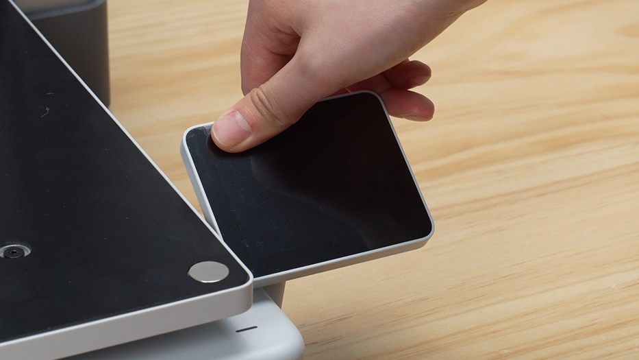
Step 15: Install the Build Plate
-
Hold the build plate with both hands, align the edges with the heatbed, and gently lower it.

Step 16: Remove Protective Films and Tapes
-
Remove the screen and SD card protective films.

-
Remove the tape from the toolhead.

-
Remove the tape from the front and back of the X-motor box.

-
Open the privacy cover.

Step 17: Install the External Spool Holder
-
Take out the external spool holder and attach it to the frame.

-
Take out the PTFE tube, connect one end to the tube connector on the holder, and the other end to any one of the filament inlets on the toolhead.

Part 3: Power On and AMS lite Multi-color System Assembly
Step 18: Power On the Printer
-
Insert the power cord and turn on the power switch.

Step 19: Install the Automatic Material System (AMS lite)
- Assemble the four roller feed accessories of the AMS lite according to the color correspondence.
- Then use the dedicated screws provided to firmly attach the bottom structure of the AMS lite to its dedicated base.


-
Following the engineering logic of "short tubes connect to near ends, long tubes connect to far ends", connect the 4 filament guide tubes sequentially to the four main feed ports of the AMS lite.


Finally, connect the other ends of the four sets of filament guide tubes to the four-hole manifold input port at the top of the printhead, completing the multi-color automatic printing assembly.

Step 20: Complete Initial Calibration According to Screen Prompts
-
Ensure that the build plate is correctly attached to the heatbed. After the printer starts, follow the UI prompts on the screen to complete vibration compensation, automatic leveling, and initial system startup calibration.
Tip: If you skipped network connection and Bambu Handy mobile app binding during unboxing, you can always go to the settings page to reconfigure Wi-Fi and device binding after the machine is fully calibrated.

💡 Which users is the Bambu Lab A2L suitable for:
-
3D Printing Beginners: The A2L is the upgraded successor to the best-selling A1. For a device positioned as extremely user-friendly, plug-and-play, and fool-proof, its price and performance-to-price ratio offer dominant competitiveness. If you don't want to bother with hardware parameter adjustments, this is the most suitable choice.
-
High-Efficiency Multi-Machine Farm Owners: If you have a need for large-sized models, highly stable small to medium-scale mass production, and printing materials do not involve special engineering materials, then the easy-to-operate and highly automated A2L Combo will be a powerful tool for building your high-capacity 3D printing factory farm.